How to Draw Technical Drawings for Customizing Services
Technical drawings are essential for quote and ordering customized enclosures.
Otherwise sketch drawings are also acceptable if all the information and intentions are available on them.
The most important thing about technical drawings is that all the information can be obviously recognized by all who take a look at them.
Utilize free downloadable data provided by TAKACHI for all products to create your own technical drawings, either in CAD or sketch, inquire customizing services.
Dimension Unit
We only accept dimensions in millimeters (mm).
If you use a unit other than mm, please convert it to mm.
Scale of the Drawings
To minimize the risk of misunderstanding between the drawer(s) and the reader(s), 1:1 scale drawings are ideal.
However, due to the restrictions of drawing field, 1/2, 1/5, 1/10 or other scale can be used.
Conversely, you can draw in enlarged scale as 2, 5, 10 times or others if the drawings field has enough space.
Stay conscious on the scale when you draw or it may cause a discrepancy between the drawings and the finished image.
Arrangement of Faces
At TAKACHI customizing services, the components and the parts (= not assembled material) are processed individually.
Thus it is a basic principle to draw each material and part using trigonometry.
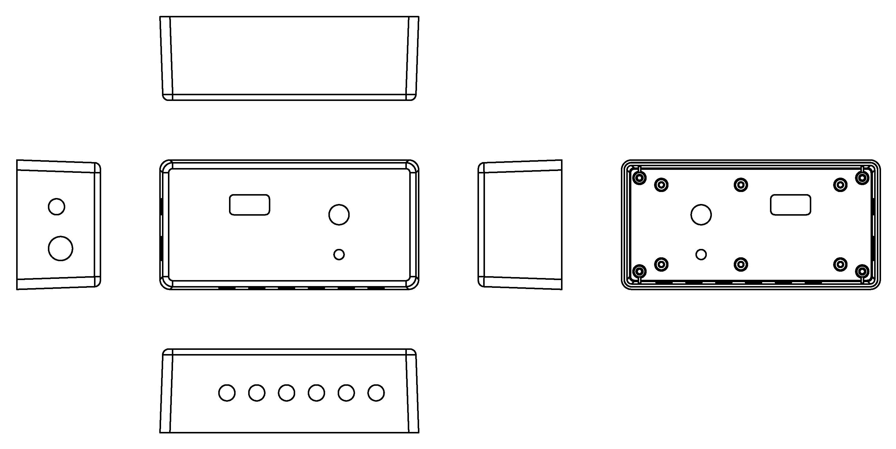
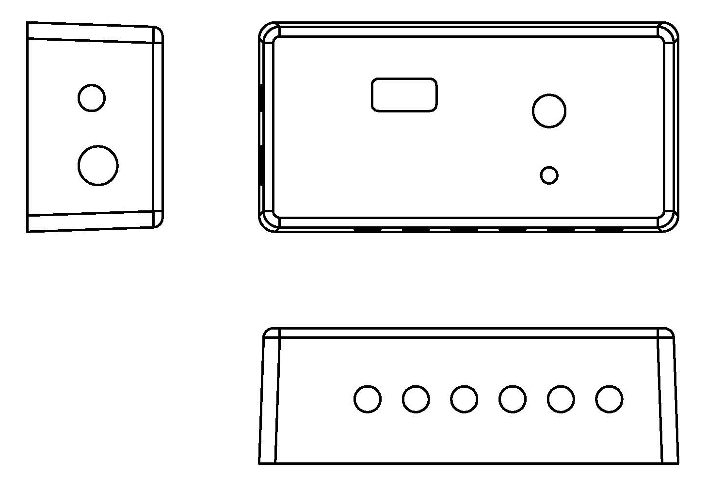
Besides, it is important to show the positional relationship of adjacent processing faces at least in a 3-view drawings if you have multiple processing faces.
6-view drawings are easier for readers but not essential.
(Third Angle Projection)
■ Explaining 6-view & 3-view diagrams with a plastic case.

【6-view drawing】
【3-view drawing】
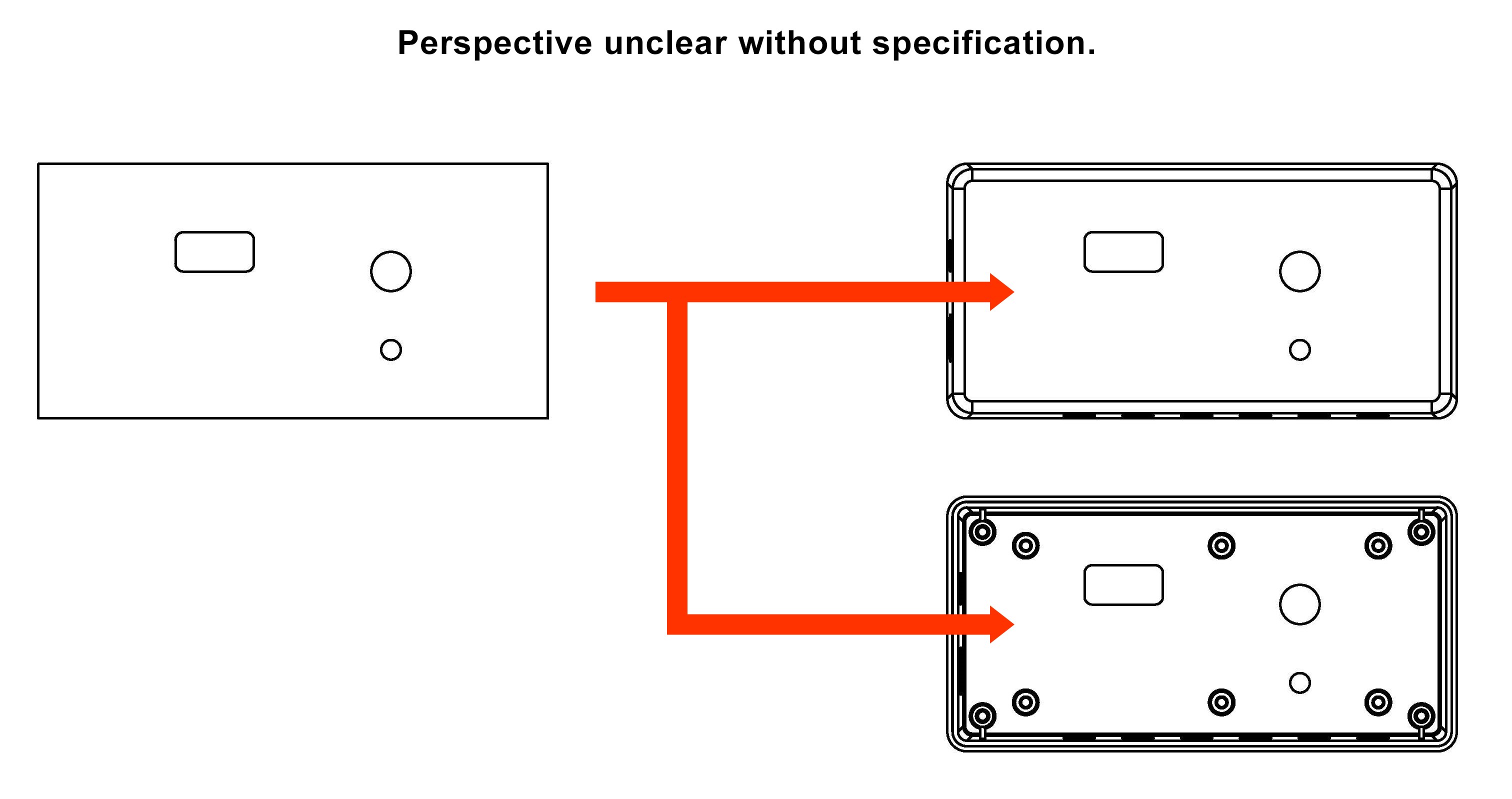
View Specifications
One of the most common problems with sketch drawings is unclearness of the arrow view.
Only the drawer knows whether the processing surface is external view or internal view without specifications.
It is important that the view has to be specified clearly.
Otherwise, the customizing may be processed upside down.
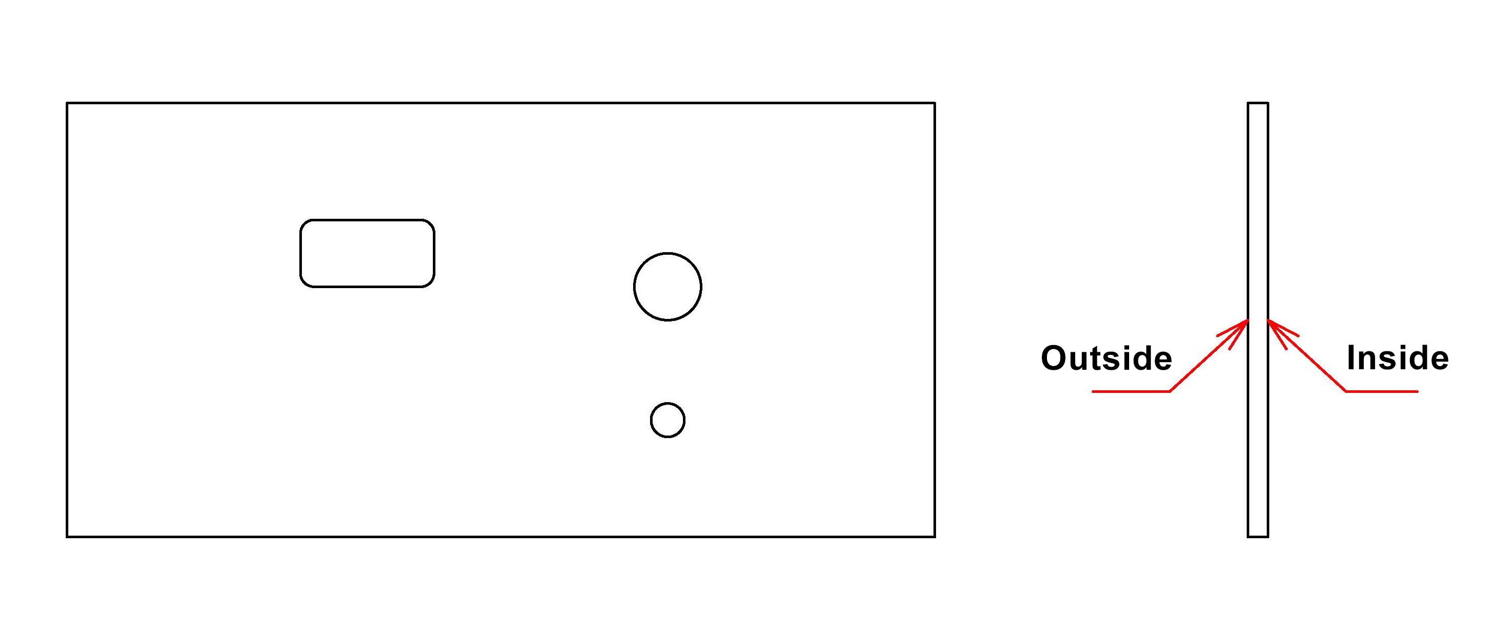
【Sketch Drawing】
For products with a tapered face(s), the view specifications can be determined by the projection drawing alone.
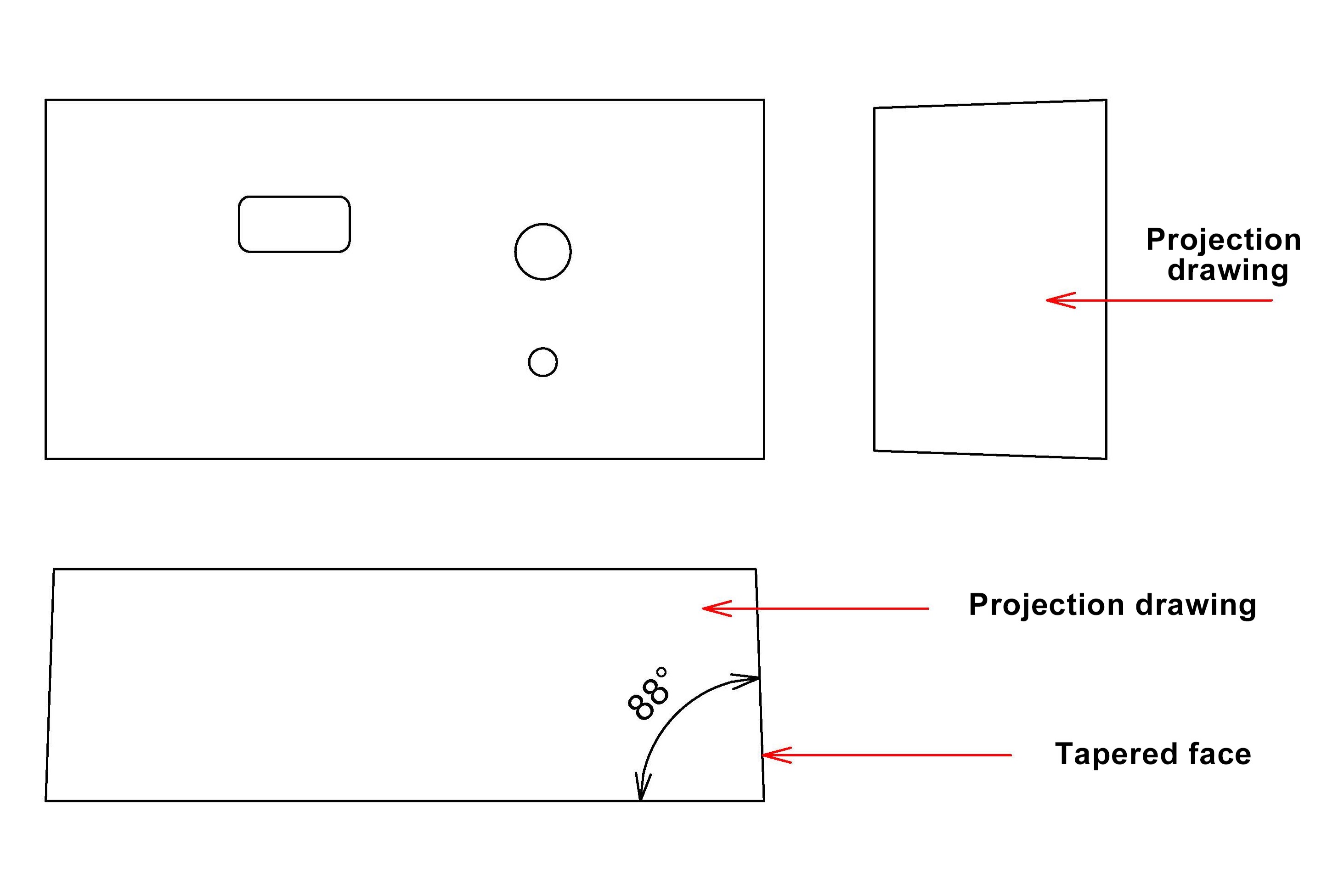
Verbal instructions are necessary for flat panel products due to identical front/back shapes.
Projection drawings do not work for flat panel products.
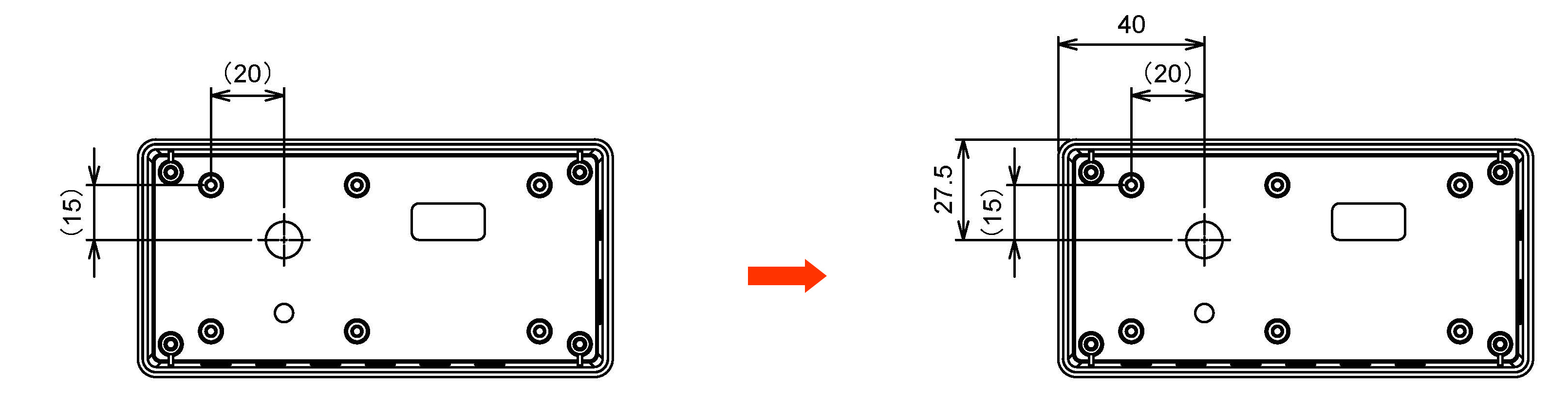
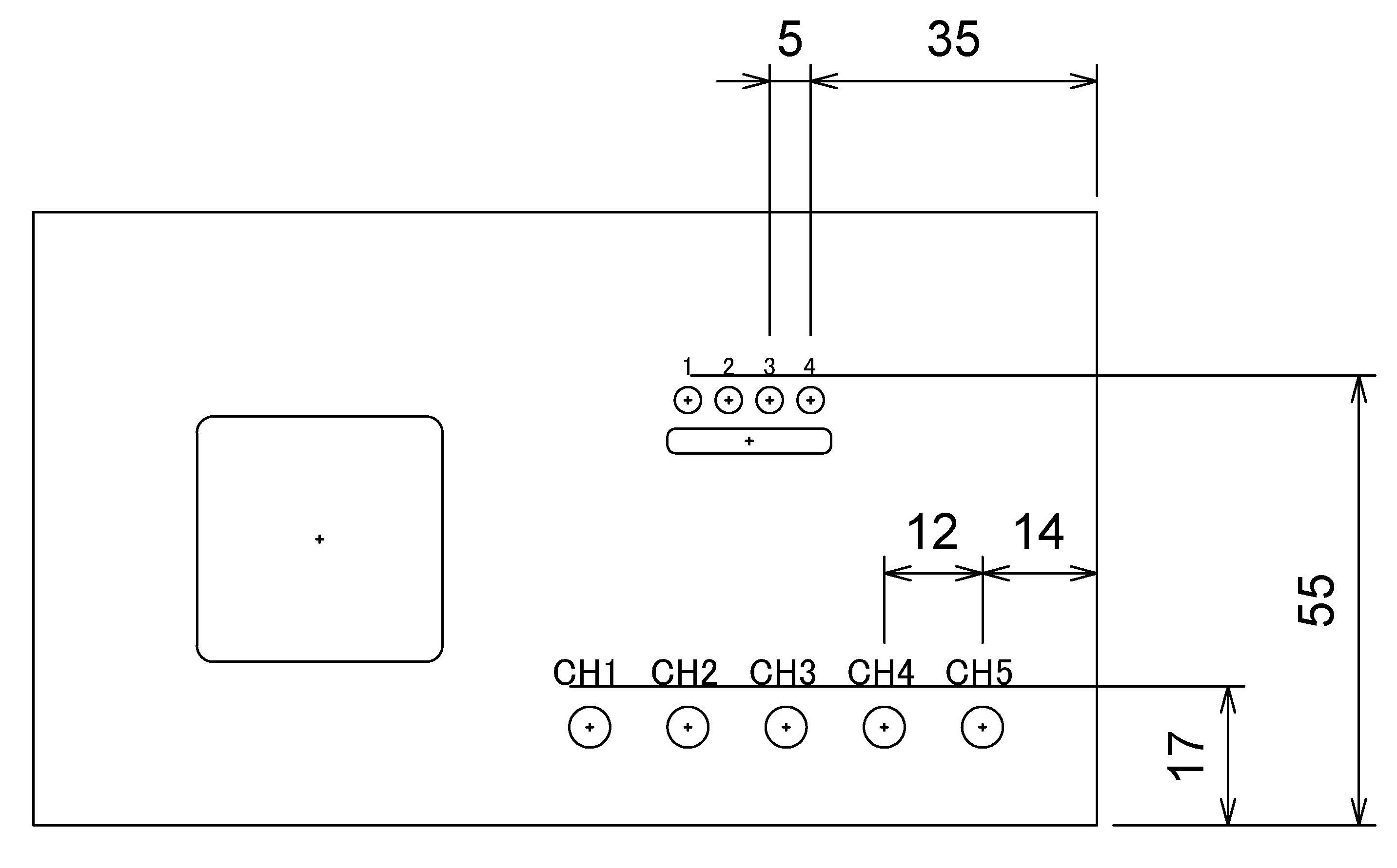
Hole Position Specifications
All the hole milling machine at TAKACHI set the origin point = 0(zero) point at the corner of the maximum outer dimensions or the very center position of the material.
Specify the distance from the center point of the designated hole to the origin point.
If specifying the distance from the bosses on material or the point where is not the origin point, the distance measure would be indicated as reference values with parentheses ( ), and the accuracy may be decreased due to the product tolerance and the processing tolerance.
【Distances from Boss Position】
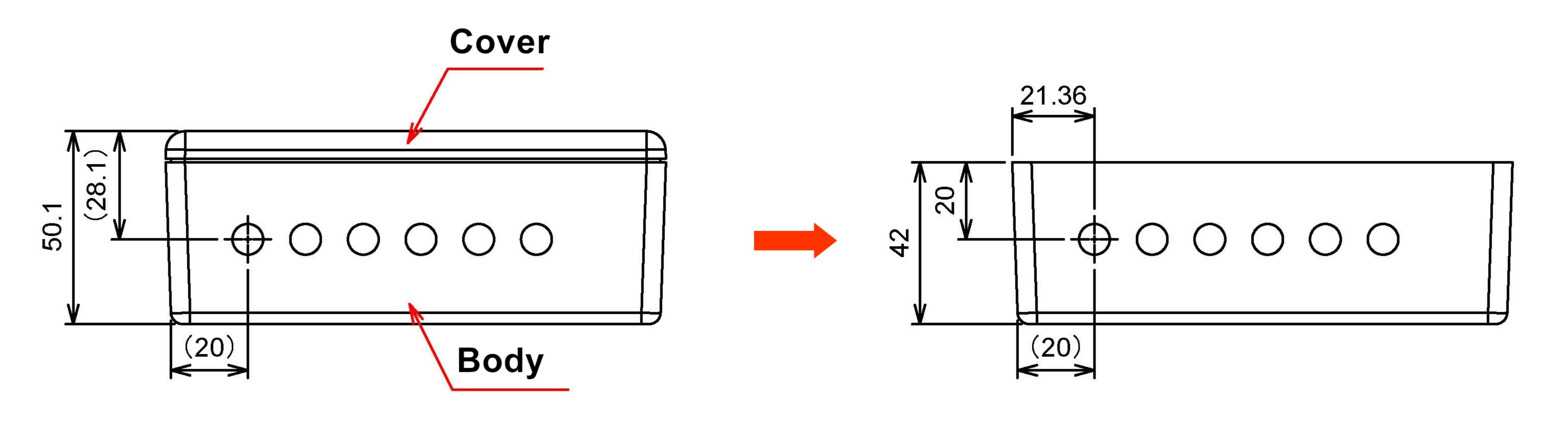
Since TAKACHI processes the components or the parts (= not the assembled material) individually, the distances on the assembled material and from the closer side of the angled components or parts are indicated as reference values with parentheses ( ) as well due to the assembly and machining tolerances.
【Distances from Assembled Material】
Dimensions and Processing Types
Specify all the dimensions in millimeter. The ""mm"" symbol is not required.
If the letters are too small and/or the lines overlap, the designated dimensions would be misunderstood by the readers.
Since the price quotation at TAKACHI is determined by the hole sizes, the numbers of holes, and types of the holes, specify the accurate information.
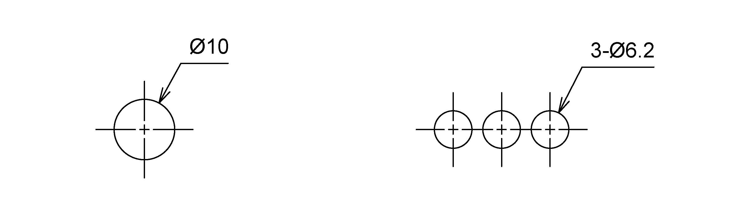
【Circular Hole】
The diameter of a circle is represented by Φ (phi).
If there are multiple holes of the same diameter, it is easier to draw them together in the form of "number of holes - diameter".
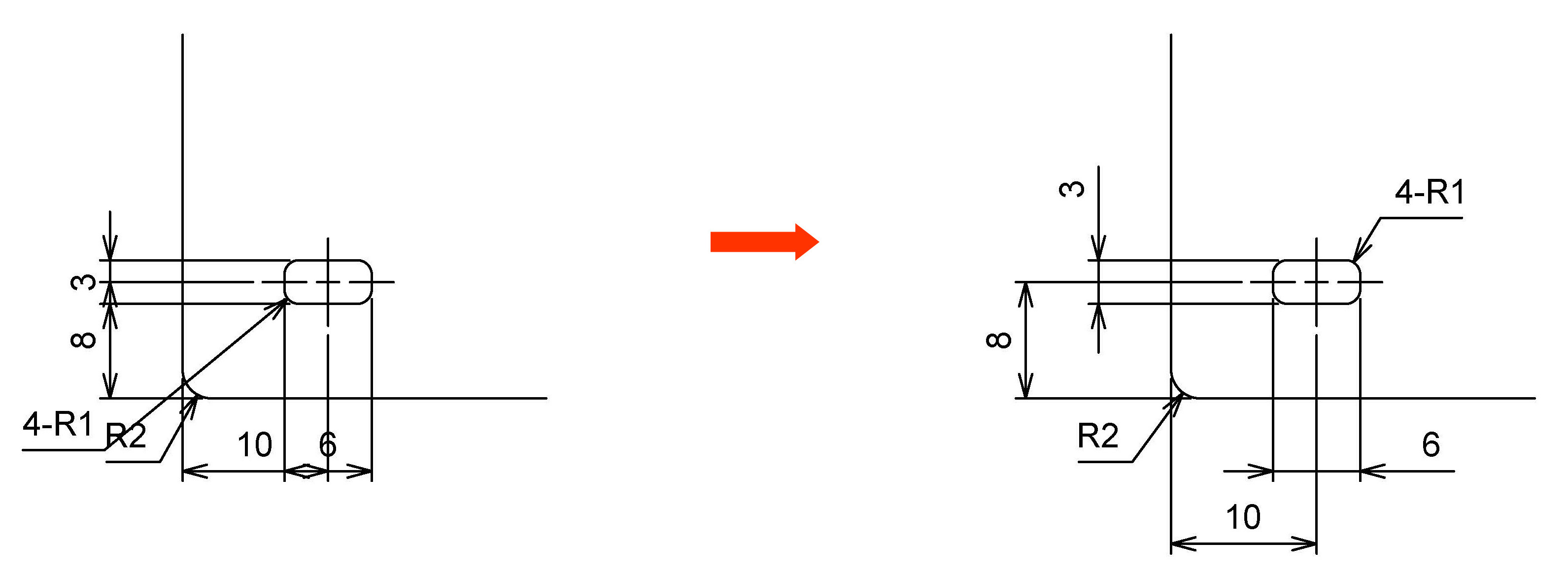
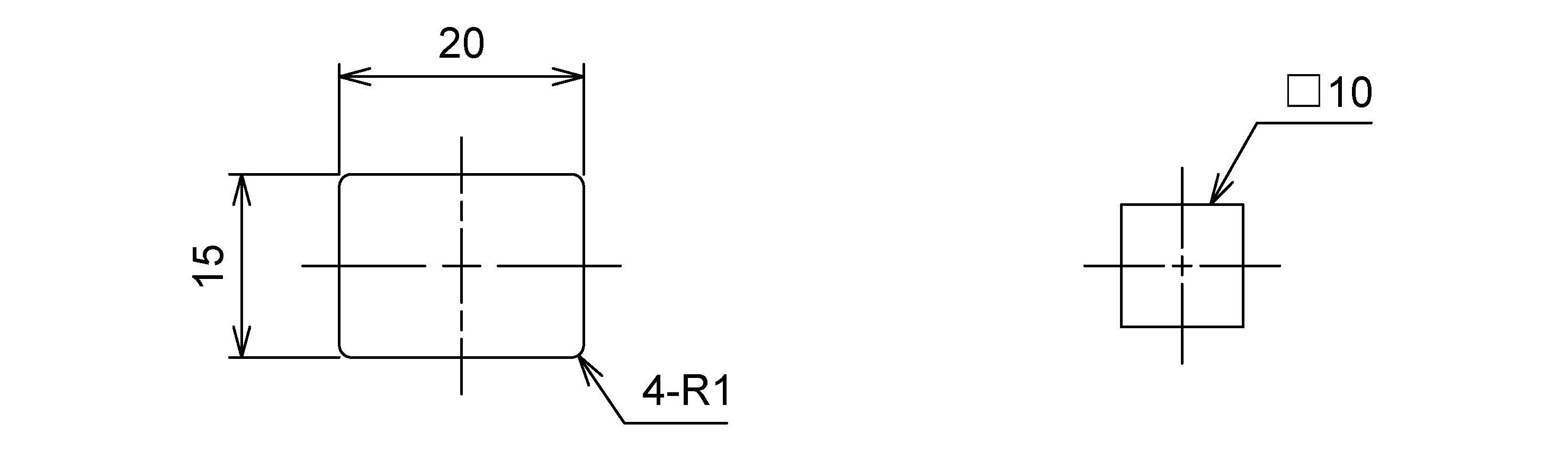
【Rectangular Hole】
Draw the dimensions for the vertical and horizontal sides.
For example, a square with a side length of 10mm can be abbreviated as □10.
On plastic and aluminum molded material, the hole making would be processed by CNC machining with round tools at TAKACHI. Thus standard R1 (1.0mm corner radius) is applied to all the corners.
Optional R0.5 can be specified.
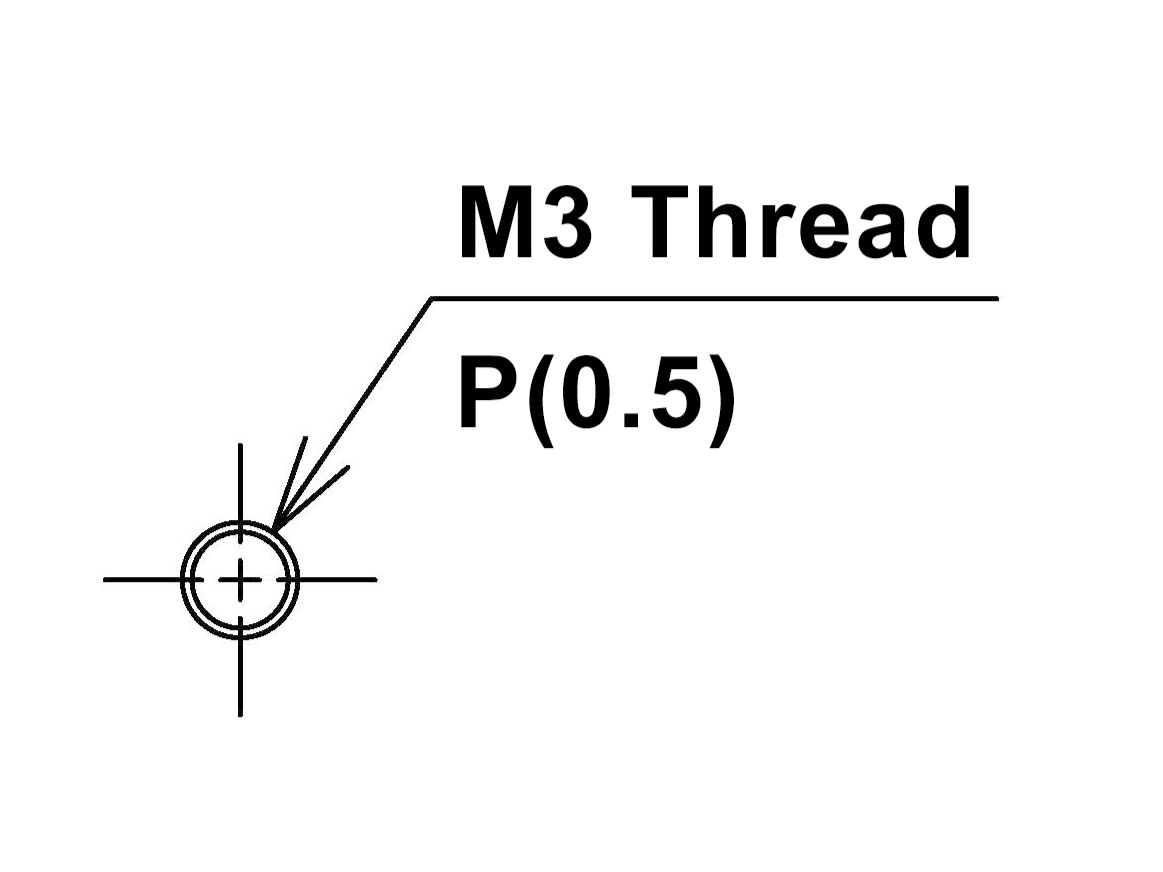
【Threading】
To distinguish it from a regular round holes, thread holes are drawn with a double solid line.
Draw the inner circle at pilot hole diameter, and the outer circle at the screw nominal diameter.
Make sure to specify the pitch as there are multiple pitches available for the same size screws.
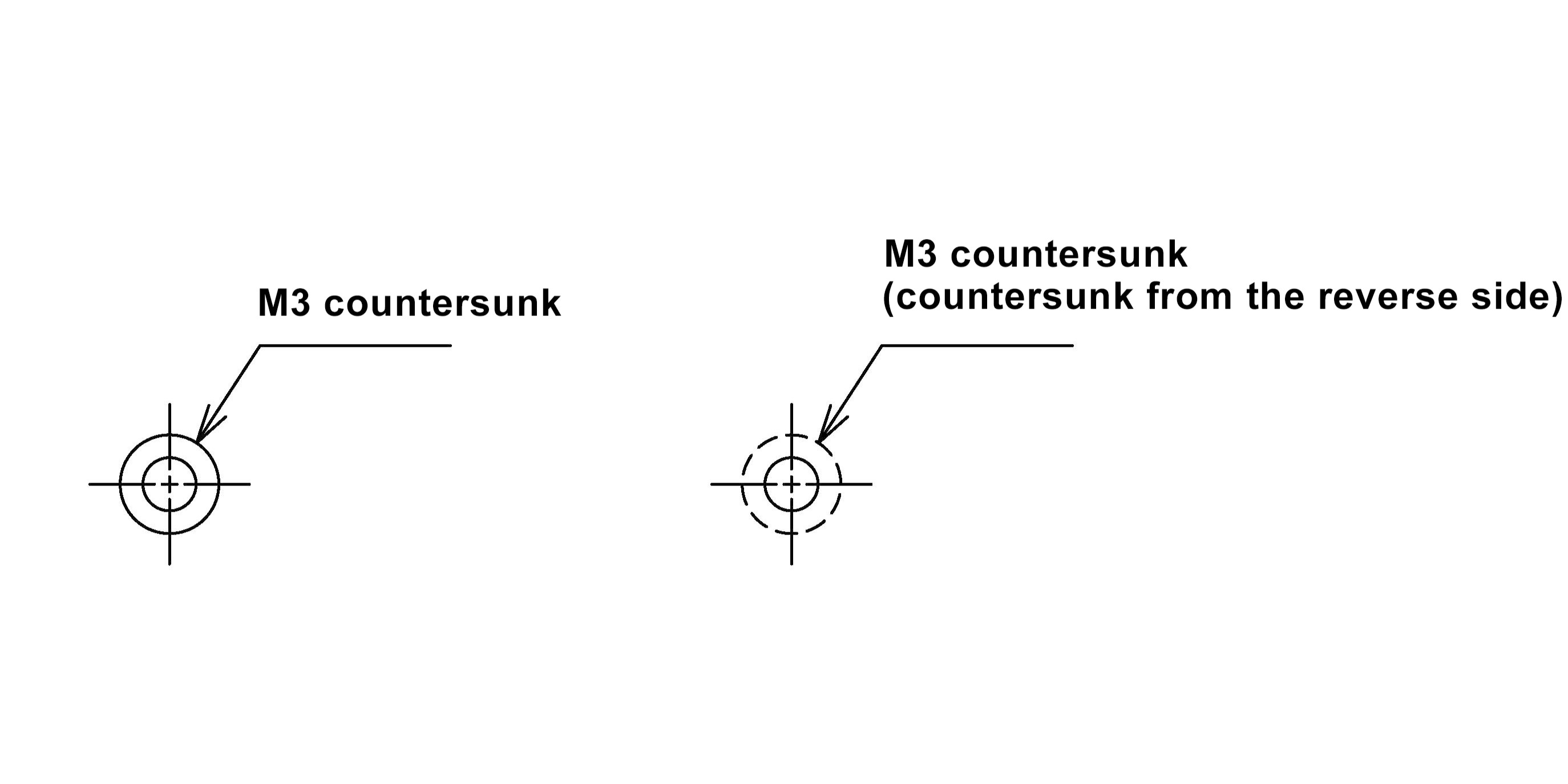
【Countersunk】
Draw a solid double circle in the same way as for the thread holes.
The inner circle is drawn with the diameter of the hole, and the outer circle is drawn with the outer shape of the countersunk.
In case of drawing the countersunk from the reverse side, draw only the outer shape as a hidden line (dashed line) and indicate "countersunk from the reverse side".
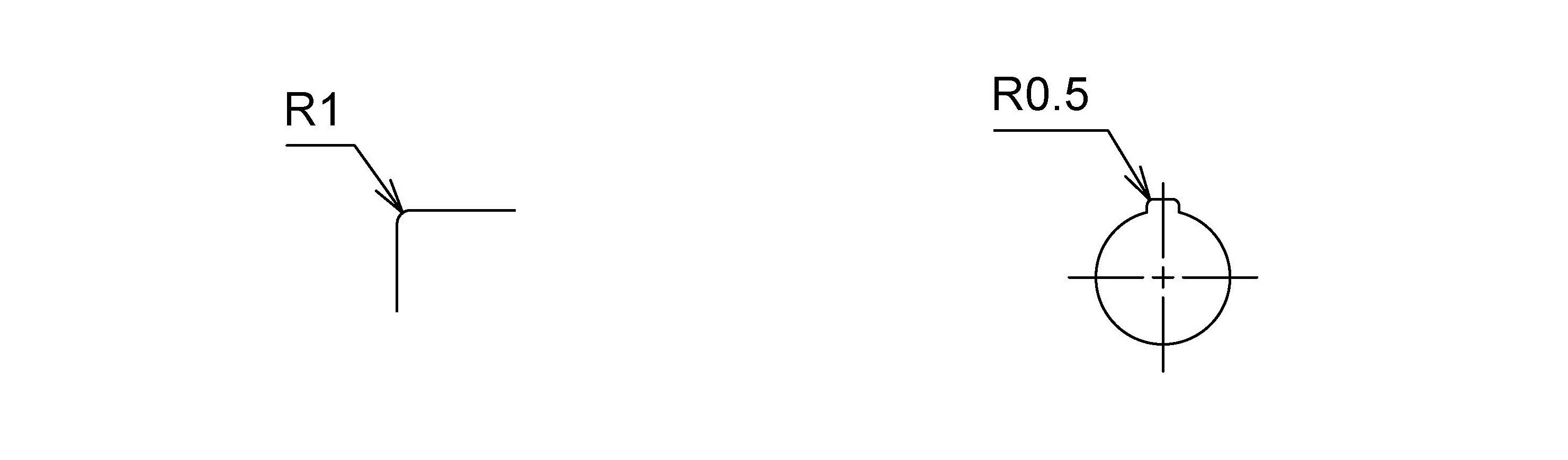
【R(Radius)】
Draw R to represent the rounding of corners for safety or aesthetic purposes.
Add number after "R" symbol to indicate the radius diameter.
For CNC machining, a standard R1 is applied to the corners at TAKACHI.
Optional R0.5 can be specified but the processing cost increases as R decreases.
Conversely, for press processing, the standard is a right angle and the cost increases if R is required.
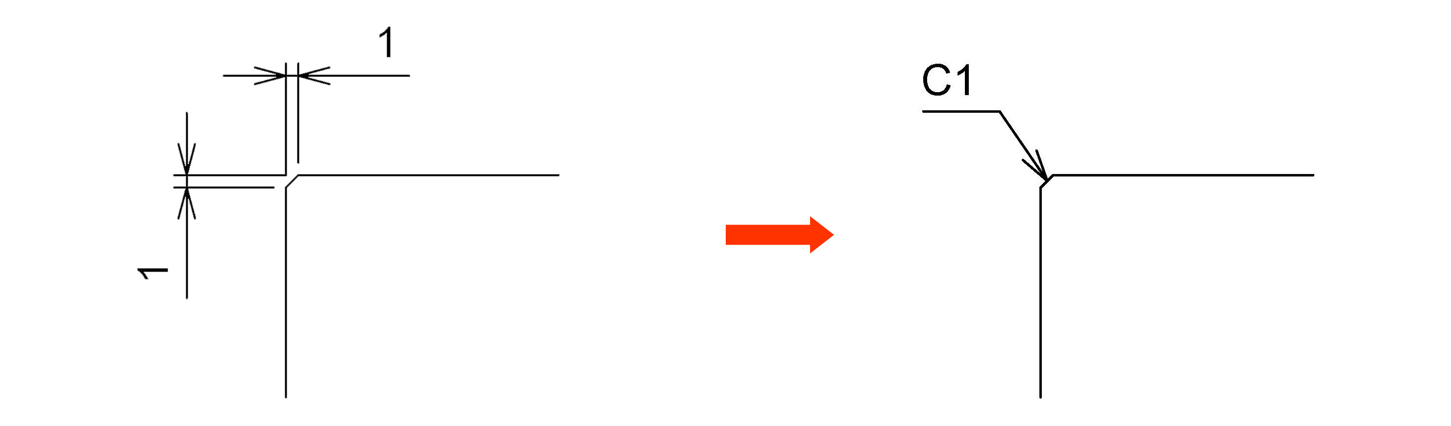
【C(Chamfer)】
C represents a 45-degree chamfer, which is also used to round corners for safety.
Draw C symbol and add a number to specify.
For example, if the horizontal and vertical cuts are 1mm, draw C1.
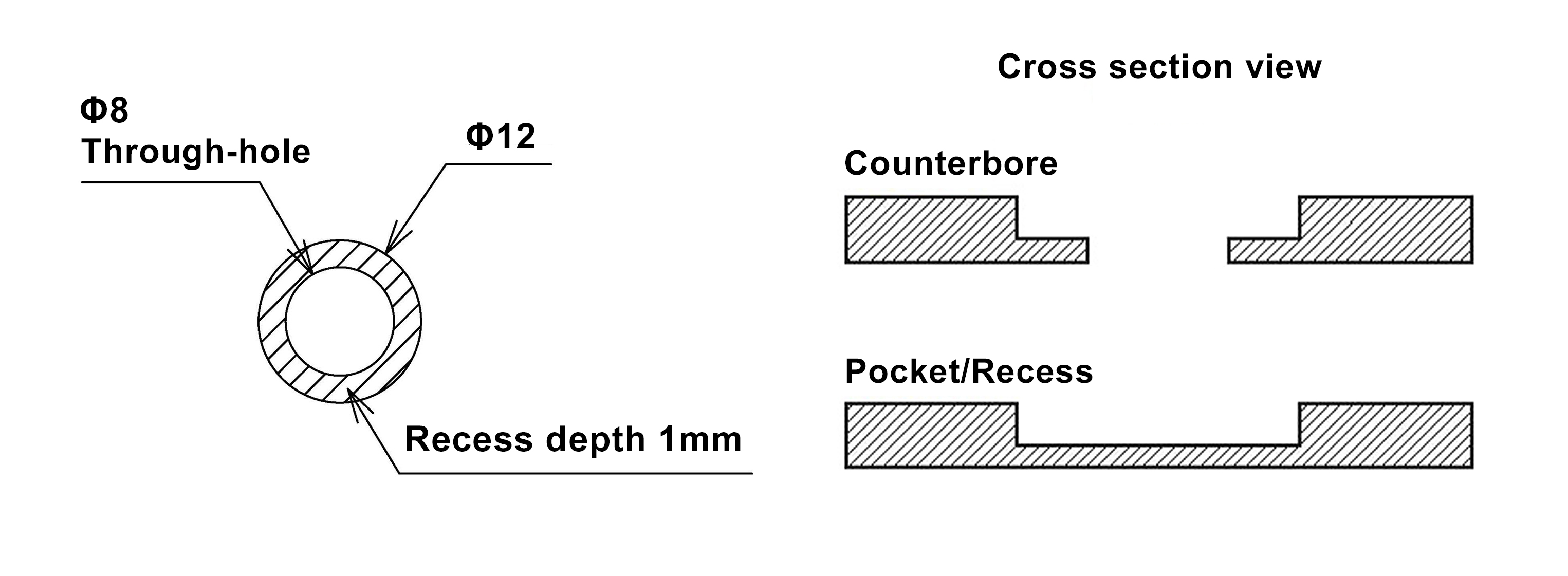
【Recess / Counterbore milling】
Counterbore is a process that creates a step, part way milling.
Useful for when installing connectors on thick material, making a recess for attaching stickers, overlays, or acrylic panels, peeling off the surface for conductivity, etc.
Recess milling without creating a through-hole is often called pocket milling.
Indicate the area to be milled with hatching and specify the depth.
There may be some variation in the depth accuracy due to the dimensional tolerance of the material.
Approval Drawings Service
TAKACHI provides a approval drawings service.
Please make sure that your drawings are complete.
If not, it may take time to offer our quotations as approval drawings cannot be drawn until all missing dimensions and uncertainties are clarified.
All the drawings for processing approval will be sent by 2D drawings.
For those who inquire with 3D data, allow TAKACHI to take longer to reply since 3D data should be converted to 2D and all the necessary dimensions should be drawn at TAKACHI.
For urgent inquiry, it is recommended to draw and send 2D data with dimensions or PDF file(s) to TAKACHI.
Letter Engraving
There are various methods for text display, such as inkjet printing, screen printing, and letter engraving.
In principle, kindly inquire with Adobe files (.ai, .eps. or .pdf).
However, sketch drawings are also acceptable for letter engraving.
Please refer to the following instructions on text display.
【Example of Letter Engraving Drawings】
|
Font color:
|
black | ||||
|---|---|---|---|---|---|
|
Font size:
|
Round Gothic | ||||
|
Character height:
|
|
The required information is color, font, character height, and position.
In order to avoid misunderstanding in the specifications, please be sure to inquire with "Processing Drawings" and "Engraving Drawings" separately.
If those 2 drawing files are combined together, it is hard to see and recognize whether the text are specifications or letters should be engraved.
Please note that company logos and complicated printing require Adobe files.